5 Minutes Timer Circuit To Turn Off Electrical Devices
A timer circuit is used to generate an output pulse after a given period of time. This time can be in the order of seconds or minutes. The length of the output pulse can be varied by changing the frequency at which the clock signal is applied to the timer's input pin.
Time interval can be measured in seconds, minutes, hours, days or weeks. Timer circuits are used in various applications such as controlling ovens and gas stoves or any electrical devices. It is also used in to control the period of time for which lights turn on or off.
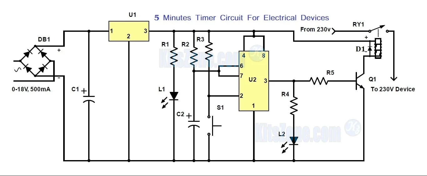
Circuit Diagram
Parts Required
Resistors: (1/4w)
R1 - 4.7K
R2 - 270K
R3 - 10K
R4 - 4.7K
R5 - 1.2K
Capacitors:
C1 - 470uF, 35V
C2 - 1000uF, 25V
IC
U1 - 7812
U2 - NE555
DB1 - DB107 Bridge Rectifier
Transformer : 0-15v or 0-18v, 350mA or 500mA
RY1 - 12V relay (Ampere based on your requirement)
D1 - IN4007
Q1 - 2N2222 NPN transistor
S1 - Momentary Switch (NO)
LED
L1 - Red
L2 - Green
General Purpose PCB
Circuit Working
This is a basic timer circuit designed using the popular timer Ic 555. Voltage from a stepdown transformer is converted to DC using bridge rectifier DB1 and is fed to the voltage regulator Ic to get a 12v regulated power supply.
555 timer IC is wired as a monostable multivibrator and the timing is calculated by the following formula:
T = 1.1RC
The component values used here to generate approximately 5 minutes. Once the preset time is reached, it will automatically turns off the device. Again, in order to turn on the device, we have to press the momentary switch S1.
L1 is used here to indicate the power to the unit whereas L2 is used here to denote the electrical device connected to the mains supply through the relay is ON.
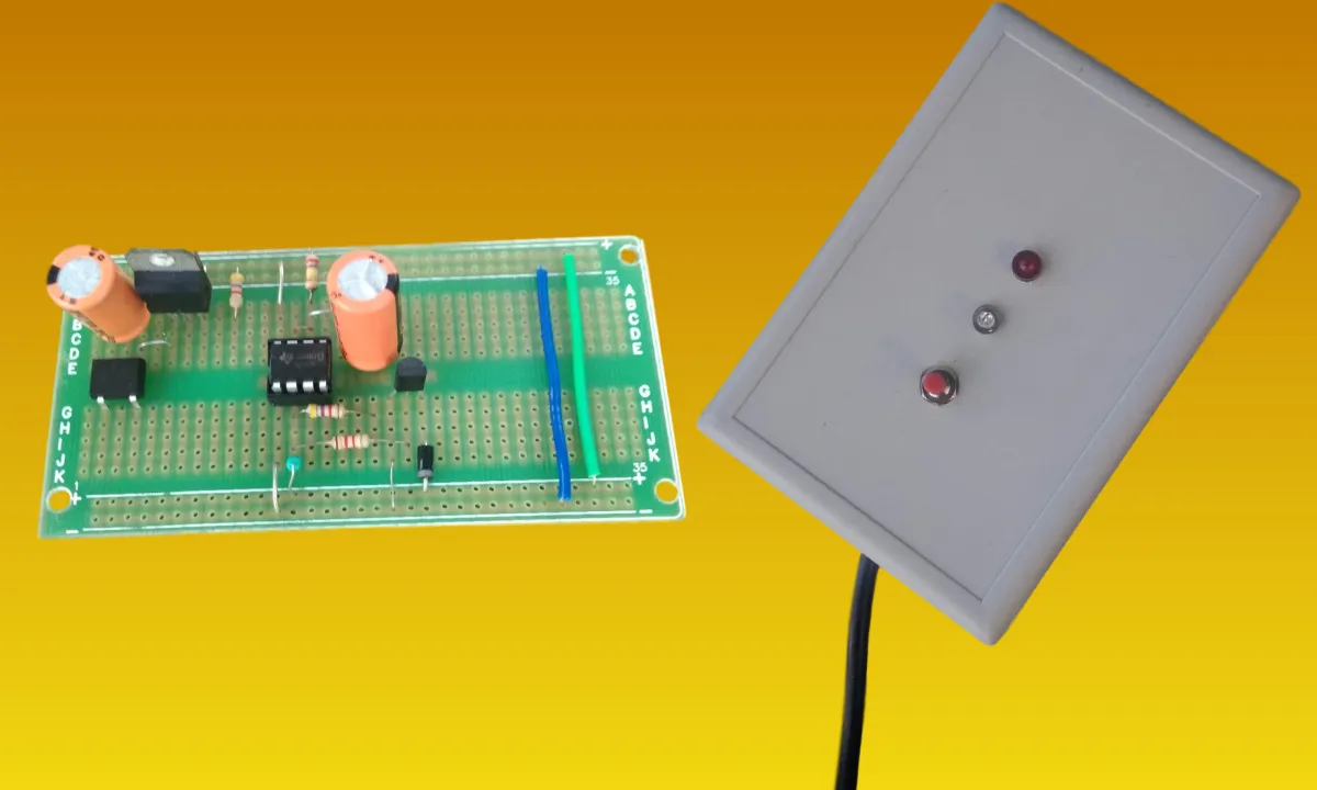
Prototype