Automatic Water Level Controller Circuit For Sump & Overhead Tank | Transistor Based
Water level controller is necessary for many reasons. Water level can be monitored and controlled automatically without any human intervention. Thus, it saves water wastage, electricity and time. This can be used both in industries and houses. The circuit I am going to share in this post controls water level in the overhead tank or any tank. Can be used in tanks of any liquids (eg. oil) provided it should not be hot. The cost of making this circuit is very low and can be assembled on a general purpose board if you are using it for your personal use.
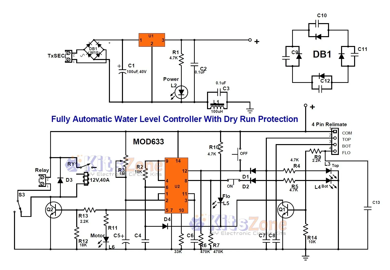
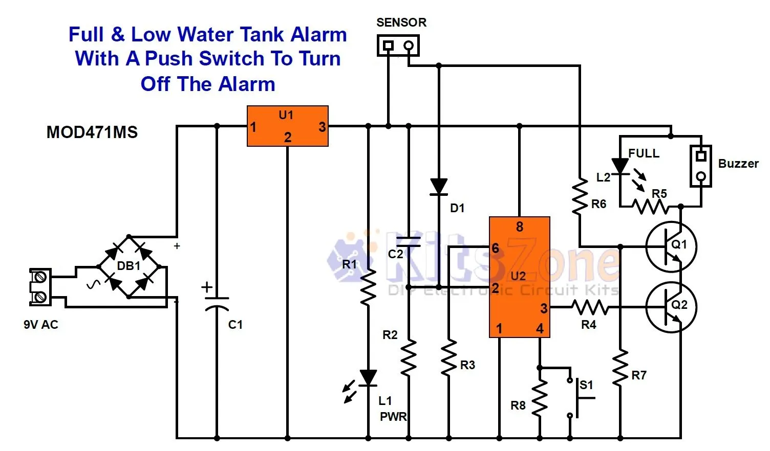
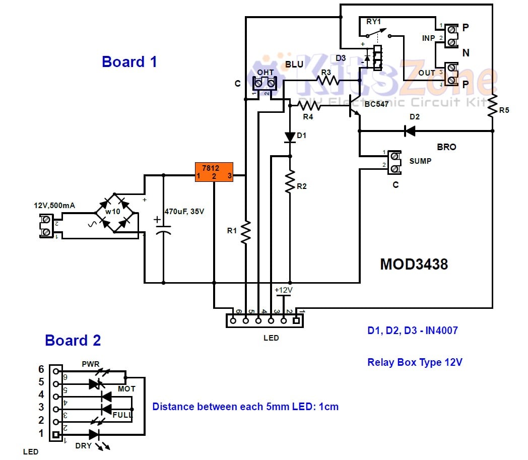
Circuit Diagram
This circuit is based on transistor. Simplified version without transistor will be published soon.
Parts Required
Transformer : 12V, 500mA or a 12V SMPS
DB1 - Bridge Rectifier W10
Capacitor: C1 = 470uF, 50V
IC U1 = 7812
Resistor: (All 1/4W)
R1, R2,R3,R5 = 4.7K
R4 = 3.3K
2 Pin PCB Mount Terminal Connectors:
Power
OHT
Sump
INP (optional)
OUT (optional)
Diode:
D1,D2,D3 = IN4007
Transistor:
Q1 = 2N2222
Relay
RY1 = 12V,40A
Circuit Working
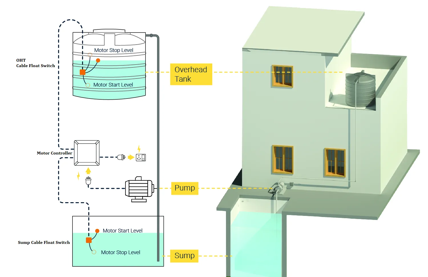
This circuit is controlled by a single NPN transistor with the help of two cable float switches. It will constantly monitor both the levels of sump and overhead tank and protects the motor pump from dry run. The unregulated DC voltage from the transformer is regulated by the voltage regulator Ic. Choosing the best quality cable float switches is very important. Float switches consists of three terminals, but, here in this circuit, we are going to use only two terminals from both float switches. Black wire is labeled as C, blue wire is labeled as BLU and brown wire is labeled BRO. Overhead tank uses black and blue wire of the float switch and Sump uses black and brown wire of the float switch.Terminal blocks for input(INP) and output(OUT) are optional because we can directly connect it to the terminals of the 40A relay.
Scenario 1:
When both tank and sump are empty,
Power LED and Yellow LED will be turned ON
Scenario 2:
When the tank is empty and sump is full,
Power LED and Motor on LED will be turned ON
Scenario 3:
When both the tank and sump are full,
Power LED and Full tank LED will be turned ON
Scenario 4:
When the tank is full and sump is empty,
Power LED , Full tank LED and Sump Dry LED will be turned ON
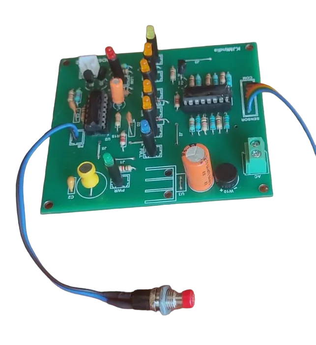
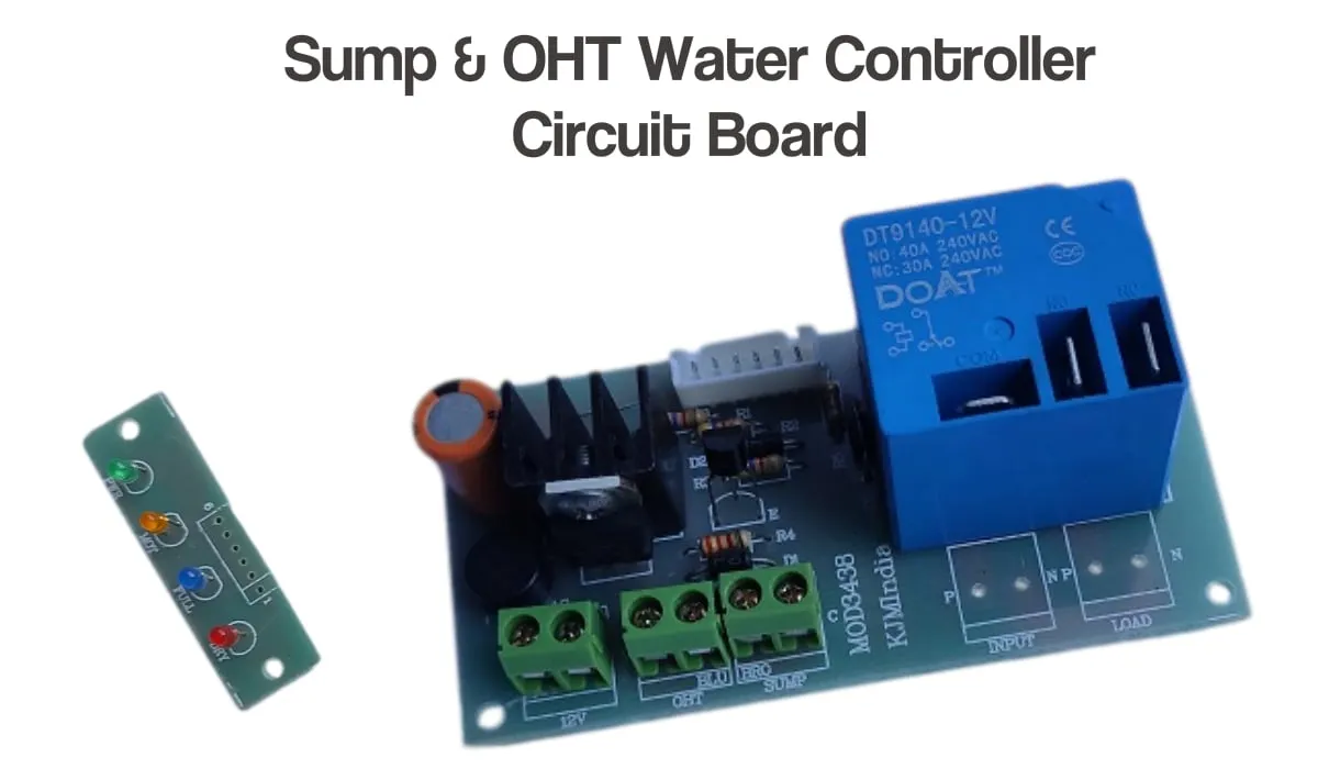
Readymade Kit
Connection Details