Battery Monitor Circuit Diagram Using NPN Transistor BC547
Battery Monitor Circuit Diagram Using NPN Transistor BC547
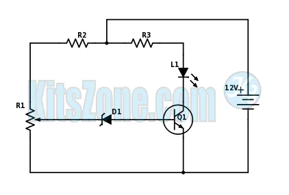
Circuit Diagram
Parts Used
Transistor : BC547 (Q1)
Resistor (All are 1/4Watts)
R1 – 10K
R2 – 1K
R3 – 1KDiode:
D1 – 6V, 500mW Zener
D2 – LED (any color)
General Purpose PCB
Circuit Description
This circuit is designed to serve as a vigilant monitor, alerting the user whenever the battery voltage dips below a threshold determined by the 10K potentiometer. It functions as an essential diagnostic tool, capable of identifying a potentially defective battery or signaling the need for recharging should the cranking of the battery cause its voltage to fall beneath the preset "safe" limit. This mechanism ensures the reliability and longevity of battery-operated devices by providing timely warnings for maintenance and intervention.