Working Theory Of A Full Wave Rectifier Circuit | Waveform | Mathematical Analysis
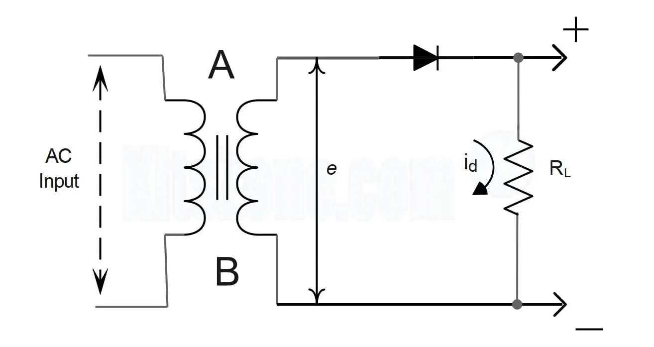
A full-wave rectifier is a device that converts the entire cycle of alternating current (AC) into direct current (DC). Unlike the half-wave rectifier, which only uses one half of the AC cycle, the full-wave rectifier utilizes both the positive and the negative halves of the AC signal to generate a more constant DC output. This is achieved by inverting the negative half of the AC cycle to positive, allowing for a smoother and more continuous flow of current than what is achieved with half-wave rectification.
There are two primary types of full-wave rectifiers: the center-tapped transformer and bridge rectifier.
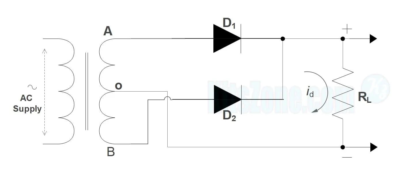
Center-tapped transformer full-wave rectifier: This design uses a transformer with a center tap on the secondary winding. Two diodes are then connected to the transformer, such that each one conducts during one half of the AC cycle. The center tap acts as the common ground or zero voltage reference point, allowing the top and bottom halves of the transformer to supply the positive and negative halves of the cycle, respectively.
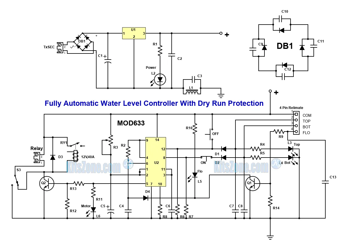
Bridge rectifier: The bridge rectifier does not require a center-tapped transformer and uses four diodes arranged in a bridge configuration. This arrangement allows for the conversion of both halves of the AC input into DC output. During each half-cycle, two of the four diodes conduct in such a way that the direction of the current flow through the load remains the same, thus producing a full-wave rectified output.
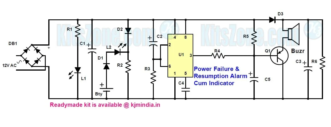
The output of a full-wave rectifier is significantly smoother than that of a half-wave rectifier, but it still contains ripples. Therefore, it is common to use a filter (usually a capacitor or an inductor-capacitor combination) to smoothen the DC output further. The full-wave rectifier is more efficient and provides a higher average output voltage than the half-wave rectifier. It is widely used in power supply units for electronic devices, battery charging systems, and other applications requiring stable DC current.
$${I_{rms}} = \sqrt {{1 \over {2\pi }}\int\limits_0^{2\pi } {id^2d\left( {\omega t} \right)} } $$
[\begin{align}
& \therefore {{{{I}'}}{rms}}=\sqrt{\frac{1}{2\pi }\int{0}^{2\pi }{\left( {{i}^{'}} \right){d}^{2}d\left( \omega t \right)}} \
& =\sqrt{\frac{1}{2\pi }\int{0}^{2\pi }{{{\left( {{i}{d}}-{{I}{dc}} \right)}^{2}}d\left( \omega t \right)}} \
& =\sqrt{\frac{1}{2\pi }\int{0}^{2\pi }{\left( i{d}^{2}-2{{i}{d}}{{I}{dc}}+I{dc}^{2} \right)d\left( \omega t \right)}} \
\end{align}]

