Overvoltage and undervoltage protection circuit diagram | High and low voltage protection circuit diagram Using LM358
Voltage fluctuations and power cuts adversely affect various electrical appliances such as Tv, music system, refrigerator, etc. Here is a simple and inexpensive circuit using opamp Lm358 to disconnect the equipment during high and low voltage.
We can also use LM324 to design this circuit by using only the two op amps out of the four. We can also design a high low voltage cut out using 741 op amp. In this case, we have to use two 741 ics.
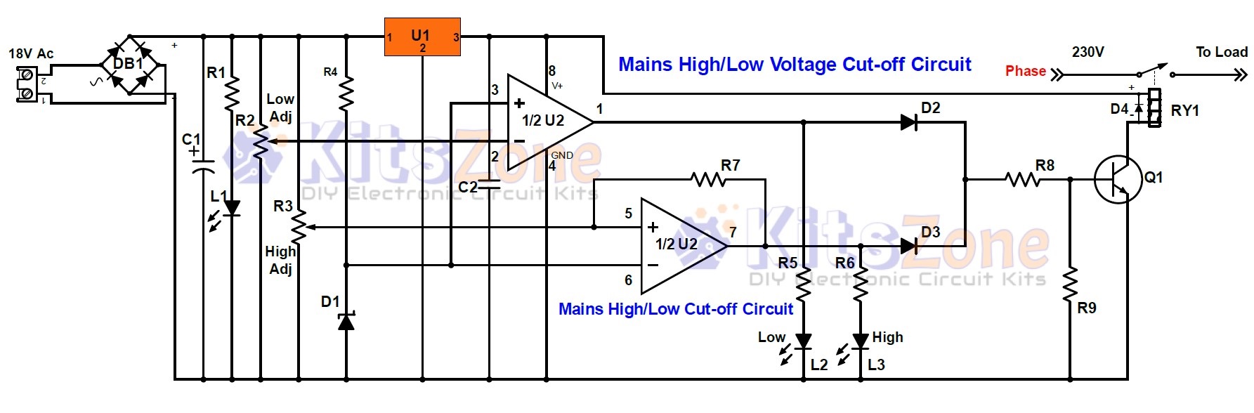
Circuit Diagram
Parts Required
Transformer: 0-18v or 9-0-9v, 300mA or above
Resistors :
- R1 – 10K, 1/4W
- R2 – 50K (preset)
- R3 – 50K (preset)
- R4 – 33K, 1/4W
- R5,R6 – 4.7K, 1/4W
- R7 – 100K, 1/4W
- R8 – 2.2K, 1/4W
- R9 – 100K, 1/4W
Diode:
- D1 – 6.2V, 1/2W Zener
- D2,D3 – IN4148
- D4 – IN4007
DB1 – Bridge Rectifier – DB107
Capacitor:
- C1 – 470uF, 40V
- C2 – 0.1uF, Ceramic
Led (5mm or 3mm)
- L1 – Green
- L2 – Yellow
- L3 – Red
Q1 – s8050 Transistor
RY1 – 12V Relay
Ic
- U1 – 7812
- U2 – LM358
Circuit Working
High and low voltages are adjusted using the Variac. High is adjusted at 260V and low is adjusted at 160V or as per your requirement. If the voltage is high, L3 will light up and if it is lower than the preset voltage, L2 will light up. In both the cases, relay will be activated to disconnect the load. Thus the appliances are protected against the voltage variation. The whole circuit can be easily assembled on a general purpose PCB.